4. The Processor > 4-1. Processor Overview
Processor Overview
Updated at 2022.10.11
Case
I will focus on handling a subset of core MIPS instructions (MIPS subset)
- The arithmetic-logical instructions:
add,sub,and,or,slt - The memory-reference instructions:
lw,sw - The conditional instructions:
beq,jump
Logic design basics
In the MIPS implementation, the datapath elements consist of
- Combinational elements
- Operate on data values
- Given inputs, a combinational element produces outputs
- e.g., ALU(Arithmetic Logic Unit), Adder, Multiplexer, AND-gate
- State (sequential) elements
- Contain state
- They have some internal storage
- e.g., instruction and data memory, registers
Combinational elements work with state elements
- Getting inputs from state elements
- Giving outputs to state elements
Clocking methodology
When data can be read and written is determined relative to the clock
In this book, we assume "Positive edge-triggered clocking methodology"
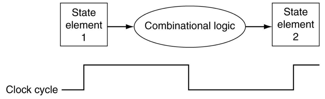
Combinational elements works with state elements
In a single clock cycle = between clock edges = between rising edges
- At one rising edge, combinational elements read inputs from state elements
- Before the next rising edge, combinational elements complete operations and produce outputs
- At the next rising edge, state elements are updated with the outputs
- The longest delay determines clock period
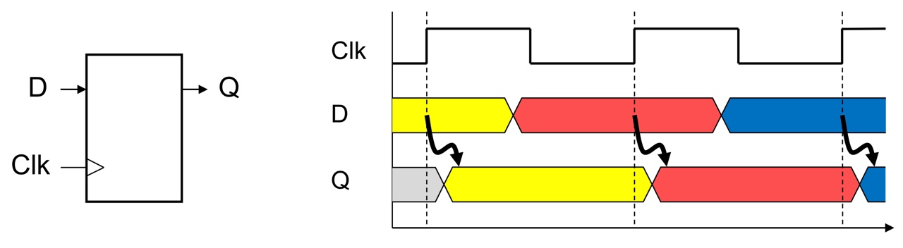
State elements with two inputs
State elements (e.g., registers) take two inputs: update data and a clock signal
Based on the clock signal, it is determined when to update the data
In positive edge-triggered clocking methodology,
Update the data at rising edges (when the clock signal changes from 0 to 1)
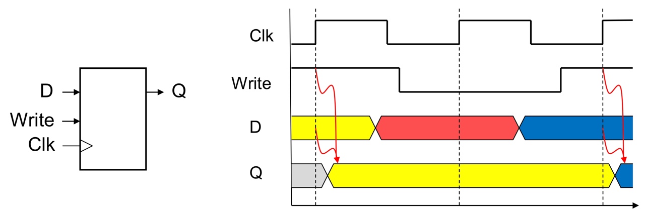
State elements with three inputs
State elements take three inputs: update data and a clock signal with write control
Based on the clock signal and the write control, it is determined when to update the data
In positive edge-triggered clocking methodology,
Update the data at rising edges + when the write control input is 1